• There has been a recent cluster of spammers accessing BARFer accounts and posting spam. To safeguard your account, please consider changing your password. It would be even better to take the additional step of enabling 2 Factor Authentication (2FA) on your BARF account. Read more here.

How-To: 2003+ Intake Cam > 2002- SV650

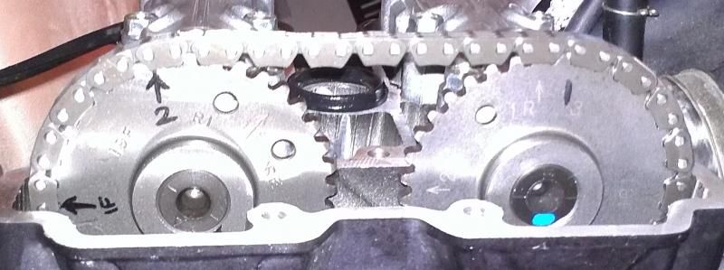
It is not about the power, the engine has a greater potential if it would run propperly. The problem here is the air fuel mixture of the front and rear zylinder in the range of 4000 and 5000 RPM. The front zylinder (RED) is too rich and the rear zylinder (BLUE) is too lean. Because of this huge differences the engine is lose power and most important it runs irregular that you can feel it.

Change one of the needles. ( raise the lean one or lower the rich one)

However you don't want to do the work needed ( check compression, cam timing) and you have not responded to any of my posts suggesting a way to fix things. I've worked on these bikes for 14 years. You just want a magical cure.
 
Change one of the needles. ( raise the lean one or lower the rich one)

However you don't want to do the work needed ( check compression, cam timing) and you have not responded to any of my posts suggesting a way to fix things. I've worked on these bikes for 14 years. You just want a magical cure.

In all respect please do not understand me wrong. I checked the compression, the heads are compleatly rebuild apart from the cam timing that will be done end of next week. I have changed the needles to the possible extream already ( raising the lean one or lowered the rich one) and the diagram is showing where I'm with all thsi already done. I guess it must be the cam timing which still needes to be done. Will report back as soon it is compleated.
many thanks for your great and valuable support

With that exhaust I suggest you try a larger main jet ( 142-148) Also check your fuel screws. If the pilot jet is 115 then set the fuel screws 2.5-3 turns out.
 
With that exhaust I suggest you try a larger main jet ( 142-148) Also check your fuel screws. If the pilot jet is 115 then set the fuel screws 2.5-3 turns out.

Many thanks, Yes will try with larger main Jet, I changed already the pilot jet from 15 to 17,5 and fuel screws must be higher as 3 turns. will need to come further down as you proposed.
Many thanks..
 
Many thanks, Yes will try with larger main Jet, I changed already the pilot jet from 15 to 17,5 and fuel screws must be higher as 3 turns. will need to come further down as you proposed.
Many thanks..

If you have 17.5 go down to 2 1/2 or less on fuel screws. 115 needs over 2.5.

Also pull up the carb slides at the same time and watch them go back down. The vacumn should retard the return equally. They need to return a bit slowly, not return quickly. (slam)
 
So I don't have my new cams yet but I've got the valve covers off so I can familiarize myself with everything to prepare. But I'm finding some discrepancies in my situation versus the write up here.

http://www.bayarearidersforum.com/forums/showthread.php?s=&threadid=154847


When I align the 'F' mark the front cylinder the front cam marks line up and looks just like the picture. However when I align the 'R' mark the rear cam markings look nothing like the picture... Even rotating the engine another 360 degrees doesn't line it up the 2 and the 3 are hardly visible. The only way I can get the Rear cylinder to look like the picture is to put it on the 'F' mark that is 360 degrees off (if lining up the Front cylinder for valve check).

Anyone know what I'm doing wrong here? Or maybe I don't need to line up the 'R' mark when doing the cam swap, there's nothing about it in the write up.

Maybe some pictures will help :

According to the write up, this is what I need the rear cylinder to look like :
IMG_9550.jpg


Rear Cylinder with 'R' Mark Lined Up for Valve check :
RMarkLinedUpforValveCheck_zps53957434.jpg


Rear Cylinder with 'R' Mark lined up, but 360 degrees off :
RMark360Off_zpsc74631b1.jpg


Rear Cylinder with 'F' Mark lined up, but 360 off :
FMarkLinedUp360Off_zps1872a21b.jpg
 
Are you confusing the "R" mark on the crank with the "R[arrow]" mark on the cams?

This picture is correct.
Rear Cylinder with 'F' Mark lined up, but 360 off :
FMarkLinedUp360Off_zps1872a21b.jpg

The crank should rotated exactly 360 degrees after doing the front and will also show the "F" mark. The cam marking you should align is the R[arrow] on the intake cam which will point to the right and be roughly level with the head surface. Then, intake 2 and exhaust 3 will line up just like in your picture.

In is also a good idea to confirm with placement of the cam lobes once you have the caps off. Their positions are depicted in the manual.

There are other timing tricks if you foul everything up. But, those shouldn't be necessary if you're methodical.
 
Are you confusing the "R" mark on the crank with the "R[arrow]" mark on the cams?

This picture is correct.


The crank should rotated exactly 360 degrees after doing the front and will also show the "F" mark. The cam marking you should align is the R[arrow] on the intake cam which will point to the right and be roughly level with the head surface. Then, intake 2 and exhaust 3 will line up just like in your picture.

In is also a good idea to confirm with placement of the cam lobes once you have the caps off. Their positions are depicted in the manual.

There are other timing tricks if you foul everything up. But, those shouldn't be necessary if you're methodical.

No, I haven't been using the 'R [arrow]' mark on the cams at all. I've only been paying attention to the 'F' and 'R' marks under the timing inspection cover. If I turn the engine until the 'F' comes up on the timing inspection cover and the front cam lobes look like \ / then the front cylinder is in position to check valve clearances. If I rotate the engine ANOTHER 360 degrees back to the 'F' mark again now the front cam lobes are no longer in position to check clearances but the markings on the rear cam look identical to the picture I posted from page one of this thread.


If I'm understanding you correctly at no time during this process do I need to align the 'R' mark under the inspection cover the only mark I will use is 'F' both ready for front cylinder valve clearances and then 360 degrees off (to set up the rear cylinder) is that correct? Or to put it another way, the only time the 'R' mark is used is just when checking clearances.
 
Last edited:
If I'm understanding you correctly at no time during this process do I need to align the 'R' mark under the inspection cover the only mark I will use is 'F' both ready for front cylinder valve clearances and then 360 degrees off (to set up the rear cylinder) is that correct?

Correct. That crank R mark is for taking the rear to top-dead-center which is unnecessary for this operation.

You will use the markings on the intake cams in conjunction with the F crank mark. The reason you need both is because the crank spins twice for every cam revolution.

Those lobes sound correct. One is \ / and the other is / \ (for TDC).

And, I slightly misspoke. The marking on the front exhaust cam is "1F[arrow]". The rear intake marking is "1R[arrow]". That and 2 and 3 with 16 links between them is all you need. The other markings are only there to confuse you.:p

[edit: I just figured out why there are superfluous markings: all the cam gears get stamped the same way as the same part is used for all 4 cams. The only difference is the orientation when pressed onto the cams.]
 
Last edited:
Correct. That crank R mark is for taking the rear to top-dead-center which is unnecessary for this operation.

You will use the markings on the intake cams in conjunction with the F crank mark. The reason you need both is because the crank spin twice for every cam revolution.

Those lobes sound correct. One is \ / and the other is / \.

And, I slightly misspoke. The marking on the front intake cam is "1F[arrow]". The rear intake marking is "1R[arrow]". That and 2 and 3 with 16 links between them is all you need. The other markings are only there to confuse you.:p

You sir are a life saver! Thank you so very much, I was racking my brain trying to figure out what I was looking at wrong. Now I just gotta wait for my cams to get here, although a quick check on my order status at Motosport.com says "No due date available" so that can't be good ha!
 
You sir are a life saver! Thank you so very much, I was racking my brain trying to figure out what I was looking at wrong. Now I just gotta wait for my cams to get here, although a quick check on my order status at Motosport.com says "No due date available" so that can't be good ha!

Sound like you're well prepared. :thumbup

Most of us just tear apart first and figure out how to put back together later, which tends to result in parts leftover.

Good luck!
 
[edit: I just figured out why there are superfluous markings: all the cam gears get stamped the same way as the same part is used for all 4 cams. The only difference is the orientation when pressed onto the cams.]

Bingo. Bill and I have gone about 2/3 of the way through a process of finding the best lobe centers and using a jig to press off cam sprockets and press them back on with a preferred location. Then the project kinda died as we got busy with other stuff. He made a beautiful jig, and I set up a motor to mark cams but it's still sitting on my bench. We do have some lobe centers we want to use. The stock lobe centers are whack, totally whack.
 
So, another question. I got the clearances set where I want them got both cylinders done was in the process of turning the engine over a few times to check everything and the front cylinder skipped a tooth. How do I know whether I need to move the Exhaust back one tooth or the intake forward one tooth? I'm assuming it's going to the exhaust since it's the one that's "pulling" the chain on around. Any quick way of telling?
 
Here's what the front cylinder looks like currently. Another reason I think the exhaust cam slipped is the 2 and 3 marks used to line up with the inside of chain link, now the 2 is on the outside of one and the 3 is on the inside still.

Both pictures are the same, just taken from different angles.

frontcylinder1_zps440aaee5.jpg


frontcylinder2_zps77e23168.jpg
 
Last edited:
Judging from the fact that the original post states the 1F mark should be parallel to the cylinder head and face the exhaust I moved the exhaust cam back one mark and it looks correct now. My only concern is that when the front cylinder is at TDC the cam lobes don't look identical. The exhaust lobe is further away from the cylinder head as compared to the cam lobe for the intake side. Can someone verify this looks correct now?

frontcylinderfixed_zps5f7c279a.jpg


Exhaust lobe that is further away from the cylinder head I can fit a finger between the cylinder head and the lobe.
exhaustlobe_zps20c5daec.jpg


Intake lobe which is closer the cylinder head and I cannot fit a finger in between the cylinder head and the lobe, is this normal?
intakelobe_zpse2d9b99f.jpg
 
Last edited:
The cams are not symmetrical. They do not open and close valves simultaneously. The manual will show you how the offset should be.
 
Alright, so after moving the exhaust cam back one tooth clockwise it looks proper now?

The pic you posted looks ok. I'd rather look at it than pics. You made the mark yourself, right?
 
Back
Top